-
Introduction
The M97 is a modern take on an idea that has been evolving for 70 years — a triode amplifier with a variable amplification factor (expressed mathematically as ‘µ’ or ‘mu’), configured to provide dynamic range compression and limiting for high-quality audio.
This project took several years to complete, and involved a huge amount of brainstorming, experimentation, and trial and error, even before the first prototype was built. Many more hours were spent rethinking, redesigning, rebuilding, and refining. The process was grueling yet fascinating, exhausting yet exhilarating. (!!) Best of all, it resulted in what we believe is an outstanding modern variable-mu1 compressor with an excellent set of features and an amazing sound.
The Design Notes below shed some light on the philosophy behind the design, while also pointing out some of the limitations found in traditional vari-mu compressors, and the solutions Electronaut devised in order to achieve a tangible improvement.
Thanks for your interest in the M97, and please don’t hesitate to send an email if you have any questions or comments!
-RRMC
Design Notes
The century-old triode vacuum tube continues to set an amazing standard of sound quality, demonstrating its persistent relevance decades after being eclipsed by cheaper alternatives. The variable-mu compression amplifier, as a single-stage, transformer-coupled triode amplifier controlled by a powerful DC amplifier, survives as a gold standard compression tool for the recording studio.
For reasons explained below, Electronaut set out to design a new variable-mu compressor with no regard for the specific character of other historical variable-mu compressors. Interest in the potential of the technique, coupled with the availability of superior components and manufacturing capabilities, demanded an attempt at producing a compressor whose capabilities were as good or better than the state of the art, and whose features provided improved usability and a more enjoyable experience.
Extraordinary variable-mu compressors already exist, so any new design needs to clear a high bar. No obvious limitations can be allowed, and no inconveniences can be tolerated. This is not a trivial task, and upon investigation it became clear that there were many problems that would need to be addressed. A small collection of some of those problems and the solutions Electronaut worked out appears below, because their descriptions do a pretty good job conveying the merits of the M97 compressor.
PROBLEM:
The most famous variable-mu compressor tube is the 6386 dual-triode, but NOS versions are hard to find and current production versions are $125 per tube!
SOLUTION:
Design the compressor to accommodate more tube options.
The performance characteristics of the classic 6386 dual triode can be equally met by a variety of tube types, many of which are in plentiful supply and at reasonably low cost. Unfortunately, none are pin-compatible with the 6386, so various modifications to classic compressors are sometimes done to accommodate these alternatives.
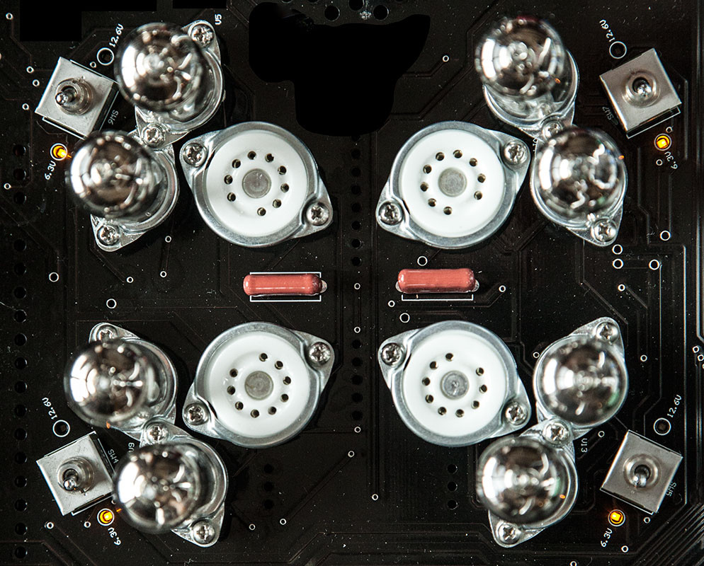
The M97 has been designed to accept many of these tube types without needing to be modified. The audio amplifier is arranged as four quadrants, each consisting of three tube sockets: one 9-pin wired for 6386 tubes, and two 7-pin wired in triode-mode for 6BA6 and equivalent tubes. Each quadrant has a switch that configures the 7-pin sockets for either 6V or 12V filaments, allowing the use of 12BA6 and equivalent pin-compatible tubes. This gives the user maximum flexibility and provides the choice of which tube type to use in each of the four sections, allowing a myriad of possible combinations.In addition to the flexible design, Electronaut has invested in a huge supply of military-grade 5749W tubes to ensure support for M97 customers for years to come. SOLVED!

PROBLEM:
Quality VU meters are harder and harder to find these days, and most of the VU meters currently available are not “true” VU meters, falling shy of the ANSI C16.5 VU-meter specification. Worse, VU meters cannot tell the recording engineer everything they need to know when working in a modern digital environment.
It’s reasonable to expect a high-end compressor to display the audio level relative to the clip-point of the recording device, but a VU meter cannot do this. It would also be nice if the meter was fast enough to indicate the effects of peak-transient reduction, and if the peak level and the average level could be simultaneously displayed, but again, a VU meter cannot do any of these things.
SOLUTION:
Design a better meter.
Dorrough Electronics in California hit the ball out of the park over thirty years ago with the introduction of their 40-segment digital LED meters with peak and quasi-average detection and display. These meters are highly regarded in the broadcast, film and post-production industries as well as the professional audio industry, but Electronaut felt that their design aesthetic was not a good fit for its products. In cooperation with Dorrough, Electronaut designed its own meter interface, utilizing the Dorrough electronics, but displaying the results in a different way.
This opened up a world of possibilities, since the meter could be employed to display all kinds of parameters, including Input Level, Post-Attenuator Input Level, Output Level, Gain Reduction, and more. By switching back and forth between these meter modes, the compressor’s effect becomes immediately visible, verifiable, and measurable, on an accurate 1 dB per-step scale, covering a 40 dB range.
Since the scale is calibrated to the dBm/dBu scale, it provides the critical reference relevant to digital systems that a VU meter cannot display. SOLVED!

PROBLEM:
Variable-mu compressors are push-pull amplifiers that must be properly balanced to minimize distortion. The metering system should have a way of indicating the balance, and a control should be provided for making the appropriate adjustments.
The traditional method is to establish a DC balance by comparing idle currents between the two sides of the amplifier, with no audio present, and making adjustments until the currents match. This method is simple and would do an excellent job if the tubes were theoretically perfect.
Unfortunately, tubes are far from theoretically perfect, and real differences exist between a tube’s characteristics at idle versus when the same tube is “swinging” volts and amplifying audio.
Traditionally, accurate tube testers always measured tubes under AC conditions, while the cheap drug-store tube testers prevalent in the 50’s and 60’s simply checked if the tube worked at all by measuring static DC conditions. DC measurements are fine for a coarse, in-the-field type of calibration, but fine-tuned results require AC measurements.
The purpose of balancing a push-pull amplifier is to minimize distortion. A perfectly balanced amplifier will cause the 2nd harmonic distortion to cancel, resulting in ‘acceptable’ low-distortion performance. This is especially important in a vari-mu because the remote-cutoff tubes required for compression exhibit fairly high levels of distortion, so cancellation is critical if low distortion is to be achieved.
Unfortunately, the traditional balancing method does not display the parameter of interest: distortion.
Lab experiments with an Audio Precision analyzer confirmed that the apparent “balance” achieved under idle conditions did not always provide the lowest distortion obtainable. Indeed, sometimes achieving the lowest distortion required a setting that appeared to be slightly out-of-balance from a DC perspective.
The best way to balance a push pull amplifier is to perform a harmonic distortion measurement, and adjust the balance control until the 2nd harmonic is minimized, but this requires expensive test equipment and an experienced technician.
SOLUTION:
Design a 2nd-harmonic measurement into the compressor!
Since we already have an accurate meter with a 40 dB range, there is no reason not to use it as a distortion meter. That allows us to discard the old coarse balancing method and replace it with a simple but high-precision method.
To implement this, Electronaut designed a very low distortion sine wave generator, and a narrow pass band filter centered around the 2nd Harmonic of the test tone. When the BALANCE option is engaged, the tone is injected into the input, the output is routed through the filter, and the 2nd harmonic is displayed on the meter. Balancing the compressor simply involves turning the balance control until the lowest harmonic level is displayed. (The output is muted whenever the BALANCE option is engaged.) SOLVED!

PROBLEM:
Traditional variable-mu compressors do not provide a way to verify the compression ratio or the effective threshold level.
SOLUTION:
Since the M97 has a built-in test tone, a 1 dB/step input attenuator, and a 1 dB/step meter, it’s possible to determine the compression ratio and the threshold level simply by increasing the input and observing the corresponding increase in output.
For example, if a 10 dB increase at the input results in a 10 dB increase at the output, there must not be any compression, the ratio is 1, and that particular range of signals is entirely below the threshold level.
If a 10 dB increase at the input results in a 2 dB increase at the output, the compression ratio is 5.
The threshold level is the point at which the 1dB step correlation between the input and output ceases. This can also be thought of as the location of the knee of the compression curve. SOLVED!
PROBLEM:
Tube regulated power supplies can sometimes drift slightly as the tubes age, requiring an occasional voltage measurement to confirm that the unit is operating within the specified range. Generally speaking, maintenance procedures are inconvenient, and everything should be done in the design process to prevent their necessity.
SOLUTION:
Come up with a way to display the high-voltage B+ supply on the meter, so it can be checked at any time, negating unnecessary maintenance procedures.
Electronaut designed a high-voltage detector circuit that essentially converts the dB meter to a voltage meter, with a 1-percent per-step scale. When the meter is set to “B+” mode, a perfectly calibrated power supply will display a level aligned to the top center “0” position. Each step above or below this position corresponds to a 1% error from the target 325V specification. It’s best to keep the power supply calibrated to within +/- 5%, and this can be checked effortlessly by switching to the B+ meter mode. SOLVED!

PROBLEM:
There’s no reason to make a tube compressor with 10-14 tubes and four audio transformers for a single channel because it’s totally inefficient by today’s standards, and there are cheaper ways to get similar results.
SOLUTION:
Test this theory on a broader scale.
If we follow this idea to its logical end, we could rule out every piece of analog gear except microphones and preamps, since everything else can be emulated in the digital domain. What’s the point of an analog compressor if we can achieve compression with a few thousand lines of computer code? Isn’t a software plug-in more “efficient” than something you have to plug-in to the wall? What’s the point of using analog EQ, or playing electric guitar through a tube amplifier, or playing a piano when you can have a keyboard, or drums when you can use a drum machine?
The implication that new techniques must mandate the obsolescence of older techniques is not supported by history. People still use analog tools to make music, just as musicians still play real pianos and drums, and guitars through tube amplifiers. The fact that new, and in many ways more practical alternatives have been developed is terrific, but that does not mean the old methods can’t continue to produce world-class results. Digital pianos have come a long way too but no one disputes the superiority of an “inefficient” 1200-lb Steinway grand!
PROBLEM:
Does the world really need another monster tube variable-mu compressor? Aren’t there already enough Fairchild clones available?
The answers are unequivocally YES, and YES.
The year 2015 marks 109 years since the triode vacuum tube was invented in Chicago in 1906. As we look back over this incredible span of ingenuity, a trend-line immediately reveals a constant and incremental progress, with creative people picking up where others left off and pushing things a little bit further, inspired by limitations they thought could be improved upon. Every single audio equipment designer throughout history benefited from the work done by their predecessors, and the trend of incremental progress happened because people were driven to look forward and think of new ideas. The engineers that created the tools we musicians and recordists depend upon generally shared three key things: a willingness to study and learn from the past, a solid understanding of the present, and a creative vision for the future.
Something interesting started to happen within the last two decades: musicians and engineers began to realize that despite a century of constant progress, many old designs still held their own against new designs, and in a lot of instances the older designs simply sounded better. 100 years of constant improvement had also been heavily influenced by 100 years of economic interests, and the result wasn’t always good for the sound. This realization, combined with the emergence of internet auction services and a globally interconnected world, inspired a frenzy of trading in vintage electronics, which in turn inspired a frenzy of manufacturers reissuing vintage designs.
Deeply rooted in Electronaut’s philosophy is a belief that audio equipment design should be informed not only by an engineer’s perspective, but also from a musician’s perspective. If we consider gear design from a musician’s perspective, some things immediately become clear: cloning other people’s designs from the past is basically the same thing as being in a cover band. Cloning is an attempt to celebrate the work of people who left behind a legacy that still may have untapped market potential, just as a cover band may find paid work playing other people’s songs. There’s nothing wrong with that, and there are many examples of designers who have labored tirelessly to reproduce every detail of a vintage design to exacting standards, flaws and all, just as there are musicians who have labored tirelessly to perfect every riff in the Beatles’ discography. A lot of people really want to hear songs from the past performed live, so naturally someone will step up and provide such an experience. That’s just how the world works.
But the world works in other ways too: people are creative and not everyone is interested in mimicking other people’s original ideas. Many people have their own ideas, and that’s the reason we have new music and art and books and movies.
For some people, admiration for the great audio equipment of the past reaches a fever pitch, resulting in a belief that these past works are so perfect that they can never be improved upon. Again, viewed from the musician’s perspective, this seems totally absurd — try convincing musicians that they shouldn’t write new music because great music has already been achieved!
The world needs another variable-mu compressor because the variable-mu technique is an amazing idea with a totally unique sound that has stood the test of time, and continues to show new potential even in a vastly different technological world. Simply stated, the idea still works amazingly well, yet there is still plenty of room for improvement.But does the M97 sound like a Fairchild or not?
The M97 is a heavy-duty, single-stage variable-mu compression amplifier with a fast and powerful controlling amplifier, and as such it shares many of the qualities that made the Fairchild 660/670 sound the way it does. However, no attempt has been made to mimic its limitations. Instead, Electronaut designed a series of improvements that just make sense in a 21st century vari-mu, including: continuously-variable attack and release controls instead of a small number of fixed time constants, a higher-current controlling amplifier providing faster attack and improved peak transient reduction capability, a significantly-improved balance calibration method for reduced distortion and thump-free operation, Lundahl transformers for improved frequency response and optimal interfacing, a 24-position balanced bridged-T input attenuator, and a vastly superior dB-accurate metering system displaying input and output level, threshold level, gain reduction, 2nd harmonic distortion, and even peak transient reduction!
Ultimately, the important distinction is the circuit topology itself: the Fairchild was a single-stage compressor with a powerful controlling amplifier, and at the time it was arguably the best implementation of that particular technique. What made it such a great sounding compressor was not that it had a magic combination of flaws; what made it great was that it expanded the potential of the topology to the extent that it could handle nearly any type of program material — something previous variable-mu compressors could not achieve.
One of the main advantages of the single-stage approach is an incredibly simple signal path: an input transformer, a tube amplifier, and an output transformer. Not even a single capacitor is present in the signal path. By contrast, many other tube compressors economize on the vari-mu stage and add additional capacitively-coupled gain stages to make up for it, but this is a move in the direction of a more complex signal path, which in Electronaut’s belief, is fine when necessary but less than ideal.
Simpler is almost always better, and the single-stage concept achieved simplicity while offering total control of the audio’s dynamics. Electronaut chose to use this approach as its jumping off point, and to try and hunt down things that could be improved, not only in terms of sonics, but in usability, interface, and features.
In Electronaut’s view, the prevailing spirit of pro audio equipment design is the desire to constantly create and improve, just as a musician may create and improve for a lifetime. An environment where recordists exhibit a healthy resistance to stagnation and the status quo is better for every musician who ever wants to make a record. We can let the luddites be luddites without criticism or judgement, and remember that they don’t have to stand in the way of new ideas.
With this spirit in mind, Electronaut humbly presents the M97 Compressor/Limiter. I couldn’t be happier with the results, and I can’t wait for you to hear it!
- The term “variable-mu” was registered as a trademark by Manley Laboratories in 2002. It should be noted that our use of the phrase, as a description of the 70 year-old compressor circuit topology, is intended to be consistent with the historical and colloquial use of the phrase, and should in no way be confused with a particular product or brand name. ↩
-
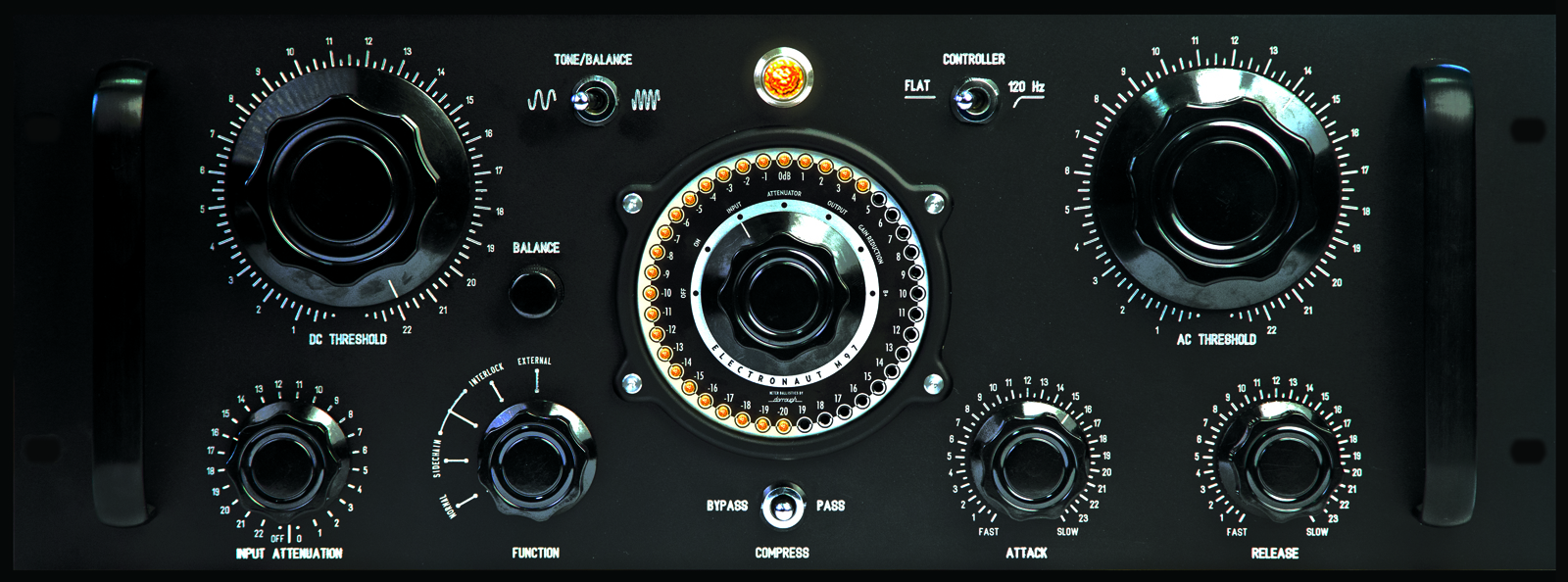
FRONT PANEL FEATURES
THRESHOLD CONTROLS
The AC and DC threshold controls affect the audio reaching the controlling amplifier, and therefore determine the type of compression or limiting the M97 performs. Both Threshold controls are 24-position stepped attenuators built on Elma rotary switches.
The AC Threshold acts as an input attenuator to the controlling amplifier; it controls the amount of limiting action, and effectively, the slope of the compression curve.
The DC Threshold selects the portion of the audio waveform that reaches the controlling amplifier, affecting the limiter’s response.
The figure shown below illustrates the effect of the AC and DC Threshold controls.
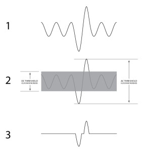
Waveform 1 represents a signal with an average level occurring most of the time and a transient peak happening occasionally.
Waveform 2 represents the effect of the DC Threshold, which effectively blocks out the below-threshold part of the waveform leaving only the peaks, and the AC Threshold, which controls the overall amplitude of the signal reaching the controlling amplifier (thus setting the amount of limiting action).
Waveform 3 is the result of the settings in Waveform 2 — no signal reaches the controlling amplifier (and thus no limiting action occurs) except during the duration of any peaks that exceed the DC Threshold.
The DC and AC threshold controls work interdependently; by adjusting the two thresholds it’s possible to configure the M97 as a transient peak limiter, so that the average program material remains unaffected and only the peaks are controlled, or as a compressor with a range of compression ratios.
INPUT ATTENUATOR
The Input Attenuator is a 1 dB/step 24-position stepped attenuator, built on a 3-pole Elma rotary switch, and configured as a balanced bridged-T attenuator with an impedance of 600 ohms.
The attenuator is placed between the input XLR and the input transformer, with an OFF (mute) function at the most counterclockwise position and a “soft-bypass” function at the 0dB position. The 0 dB setting makes it possible to achieve extended high-frequency response, as described below.
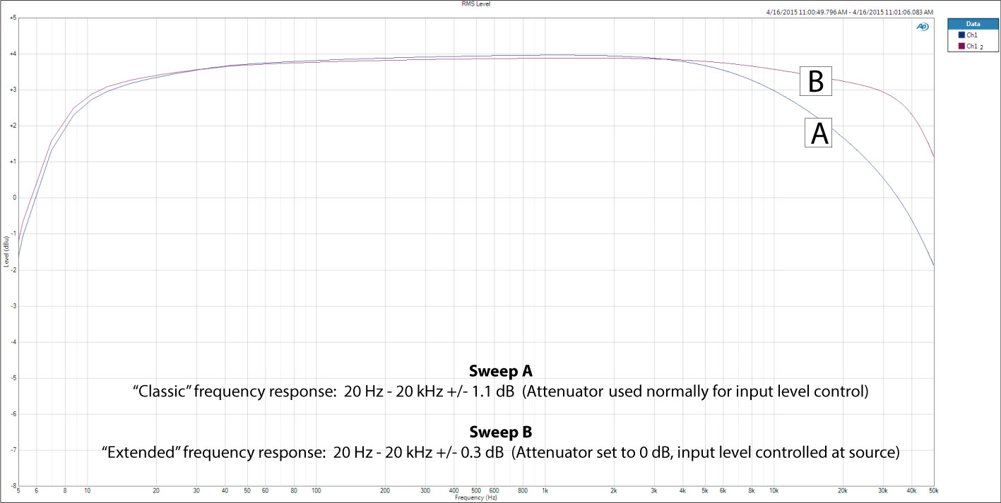
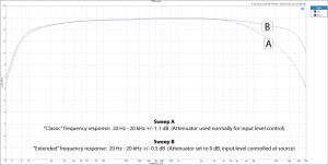
Achieving Extended High Frequency Response using the 0 dB setting
Due to the compounded parasitic capacitance caused by the sheer number of tubes used in the audio amplifier, classic compressors like the Fairchild 660/670 exhibit a high frequency roll-off of several dB at 20 kHz. This is part of the characteristic “sound” associated with this type of compressor, and was considered an acceptable trade-off for the other benefits of using so many tubes. The M97 offers the best of both worlds: “classic” high-frequency response, and an “extended” high-frequency option.
When the INPUT ATTENUATOR is set to any value between 1 dB and 22 dB, the impedance of the signal reaching the input transformer is set by the input attenuator, and the high-frequency response resembles the Fairchild. When the Input Attenuator is set to 0 dB, the impedance is determined by the output impedance of the device preceding the M97. Since modern D/A convertors exhibit a moderately low output impedance (typically between 25 and 100 ohms) the signal is less affected by the parasitic capacitance of the tubes, and the high-frequency response will be extended to nearly 50 kHz +/- 1 dB.
Since the AC and DC THRESHOLD controls determine the shape of the compression curve, and the INPUT ATTENUATOR determines where the signal is positioned along the curve, once the Threshold controls have been set the amount of limiting is ultimately controlled by the Input Attenuator. When using the 0 dB setting for extended high-frequency response, it will be necessary to adjust the amount of level reaching the M97 at the source in order to control the rate of limiting.
ATTACK and RELEASE
The attack and release controls are continuously-variable low-noise potentiometers, providing up to 50 µS attack time. The attack and release controls are interdependent. In the extreme counterclockwise positions of the attack and release controls, the limiter is intended primarily for peak limiting; where it is desirable to only trim transients and not limit the basic program material’s dynamic range.
HIGH PASS SWITCH
The FLAT/120Hz switch determines the bandwidth of the signal being fed to the controlling amplifier, and therefore the frequency response of the limiting action. Setting the switch to 120 Hz inserts a 6 dB/octave high pass filter with a -3 dB point at 120 Hz into the input of the controlling amplifier.
The high-pass filter can be useful to help keep the limiter from tracking very low frequency program material.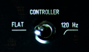
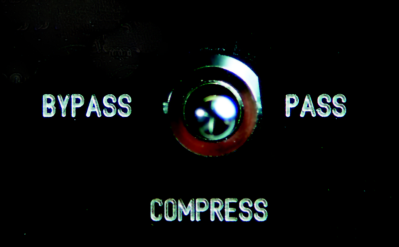
BYPASS/COMPRESS/PASS SWITCH
This toggle switch provides three distinct routing modes:
BYPASS – A signal appearing at the INPUT XLR is hardwired directly to the output, bypassing the audio and controlling amplifiers.
COMPRESS – A signal appearing at the INPUT XLR is routed through the audio amplifier to the output. The gain of the audio amplifier is determined by the limiting action.
PASS – A signal appearing at the INPUT XLR is routed through the AUDIO amplifier, which operates as a fixed-gain line amplifier with a gain of approximately 18 dB. In PASS Mode, the controlling amplifier is disconnected and has no effect.
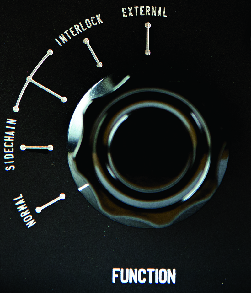
FUNCTION SWITCH
The M97 Compressor/Limiter has a front panel rotary FUNCTION switch, with five distinct modes: NORMAL, SIDECHAIN, SIDECHAIN/INTERLOCK, INTERLOCK, and EXTERNAL. They are described below in a different order for clarity.
NORMAL – The unit operates as a stand-alone limiter. Other limiters which are connected to the M97 through either the INTERLOCK or EXTERNAL buss connectors on the rear panel have no effect on its operation.
SIDECHAIN – A The limiter action is triggered by a separate audio signal appearing at the SIDECHAIN input XLR connector.
INTERLOCK – All limiters which are connected to the INTERLOCK buss connector are affected by the operation of all or one limiter – e.g., it is possible to synchronize one or more limiters for multi-channel use where the independent action would provide phase distortion under separate channel limiting.
NOTE: For stereo compression using two M97 Compressor/Limiters, both units should be set to INTERLOCK mode, and a 1/4” mono cable should connect the INTERLOCK jacks on the rear panels together.
Because the INTERLOCK mode creates a control voltage for both limiters which is a SUM of the individual control voltages, it is possible to control the limiting action using any proportion of each channel as the stimulus signal – i.e. it is possible to control the limiting action on a stereo signal with just the left channel, just the right channel, or equal parts of both, simply by configuring each compressor differently or equally.
SIDECHAIN/INTERLOCK – The limiter action is triggered by a separate audio signal appearing at the SIDECHAIN input XLR connector. Simultaneously, all limiters which are connected to the INTERLOCK buss connector are affected by the opera- tion of one or all limiters – e.g., it is possible to synchronize one or more limiters for multi-channel use, while triggering one or all limiters with the sum of a separate sidechain multi-channel signal.
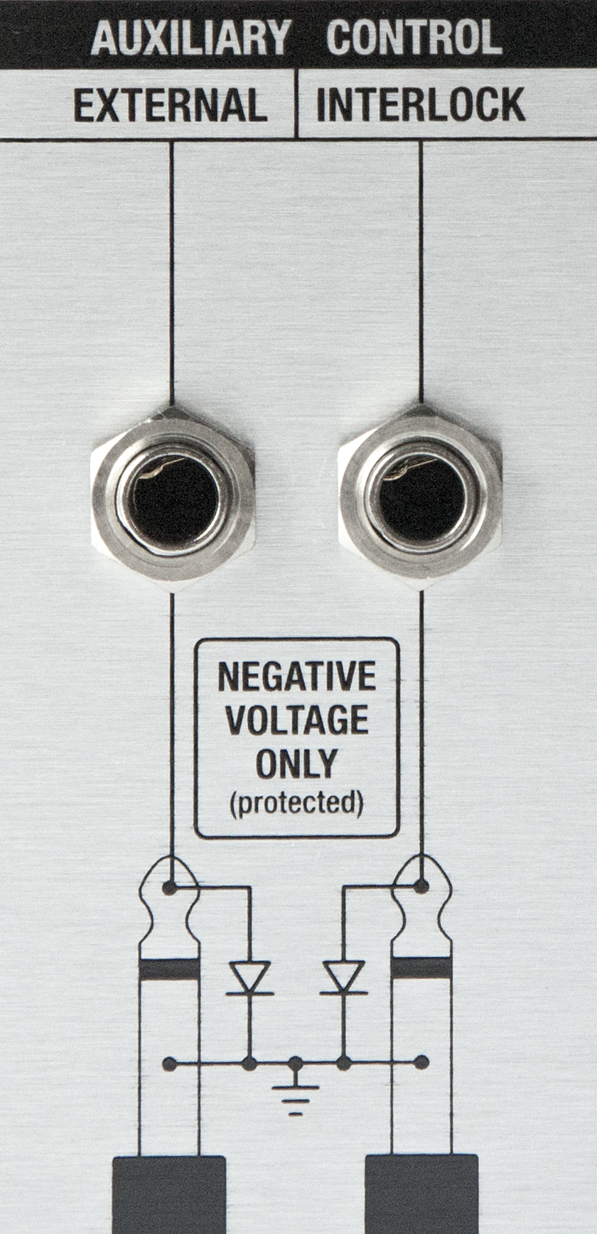
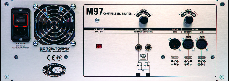
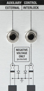
EXTERNAL – The CONTROLLING amplifier is disconnected from the limiter and the AUDIO amplifier is dependent on another limiter for its level control. A control-voltage appearing at the EXTERNAL buss connector will provide the bias to the AUDIO amplifier, and therefore set its gain. NOTE: This buss connector requires a NEGATIVE voltage which can be as low as -150 VDC for full limiting. Diode protection is present to protect against the accidental application of a positive control voltage, as indicated on the rear panel by the diode symbol.
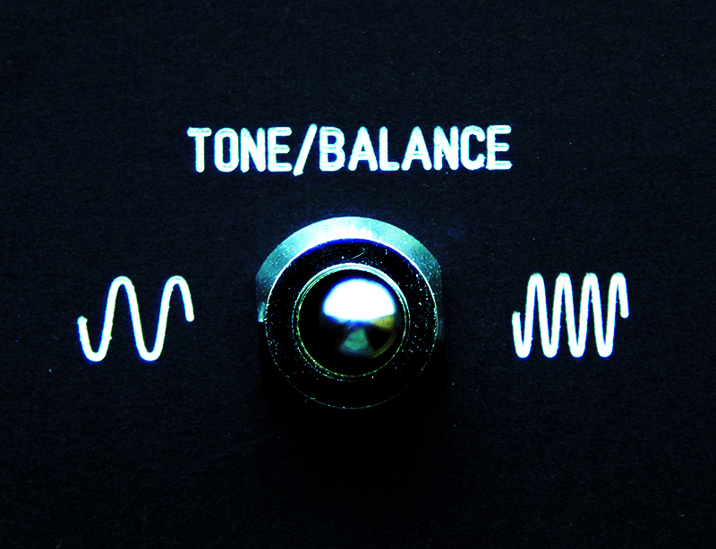
TONE/BALANCE
TONE MODE – When the TONE/BALANCE switch is set to TONE, the output is muted, and a low-distortion sine wave test tone is injected into the input of the M97. Used in conjunction with the meter, the tone makes it very easy to determine the ratio of compression and the threshold level for any combination of Threshold controls.
BALANCE MODE – As described in the “Philosophy” section, the balancing technique uses a precision sine wave test tone at the input and a narrow pass band filter at the output to isolate the level of 2nd harmonic distortion, and display it as a level on the meter. The balance is set by adjusting the 10-turn BALANCE calibration control until the minimum harmonic distortion is achieved.
NOTE: A precise balance is a theoretically correct target for minimum distortion. For distortion performance other than minimum, experiment at will! One advantage of having a precise balance control is the ease with which a recalibration for minimum distortion can be achieved after experimenting with other settings.
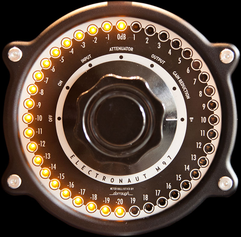
M97 METERING SYSTEM
The metering system in the M97 Compressor/Limiter represents a departure from the traditional analog meter approach. A 40 segment 40 dB Peak and Persistence meter, based on the ballistics of the Dorrough Electronics™ Loudness meter, is used in place of the usual “VU” or other analog milliammeter. Traditional analog meters typically display an RMS value of the limiting action, and are therefore unable to display a meaningful value when the compressor is set to provide transient peak reduction only. By contrast, the M97 meter has no problem tracking very fast transients, and can be relied upon as an indication of transient peak reduction.
Several METER MODES have been designed into the system, offering a myriad of advantages and providing a clear picture of how the program material is being affected by the limiting action.METER MODE KNOB
The meter is capable of several modes of display which are selectable using the center METER MODE knob. The modes are:
OFF: When the METER MODE knob is set to OFF, the M97 is in low-power stand-by mode. (See section on Low Power Standby, page XX)
ON: When the METER MODE knob is set to ON, power is applied to the main power transformer and the amplifier powers up. Allow at least 1 minute for the M97 to warm up upon startup.
INPUT: The meter displays the level of the audio appearing at the INPUT XLR connector, before it reaches the input attenuator.
ATTENUATOR: The meter displays the audio appearing after the INPUT ATTENUATOR. Naturally, an adjustment of the INPUT ATTENUATOR will display a corresponding change on the meter display. Since the meter and INPUT ATTENUATOR are both 1 dB per step, the meter and the attenuator correlate with a 1:1 relationship.
OUTPUT: The meter displays the audio appearing at the OUTPUT XLR connector.
GAIN REDUCTION: The meter displays a level corresponding to the amount of limiting action. When there is no limiting action, the meter will display a constant value of 0 dB. Limiting action is displayed in dB as a positive value, consistent with colloquial terminology – e.g., “6 dB of compression,” etc.
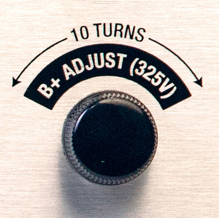
B+: The B+ meter mode converts the audio meter into a linear DC voltage meter, and is used to check the calibration of the power supply’s adjustable high-voltage regulator. A reading of 0dB indicates the power supply is perfectly calibrated to 325VDC. Any deviation from 0dB indicates a corresponding deviation from the 325V target, with each step representing a 1% error. Any reading within plus or minus 5% is acceptable.

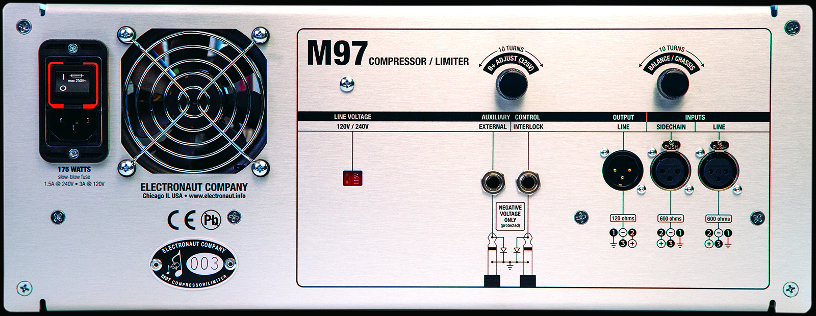
REAR PANEL CONTROLS
325V ADJUST KNOB
The 325V Adjust control is a 10-turn potentiometer used for calibrating the high-voltage “B+” supply that powers the audio amplifier tubes. The voltage value is displayed on the meter when the meter is set to B+ Mode.

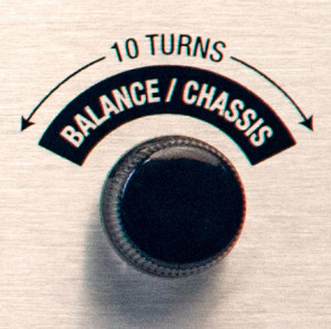
BALANCE/CHASSIS KNOB
A secondary balance control which is set at the initial time of calibration. Subsequent balance adjustments are done using the front panel BALANCE control.
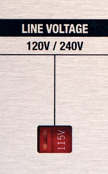
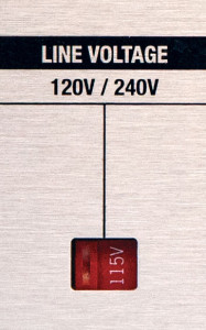
MAINS VOLTAGE
A slider switch provides two options for mains voltage: 120V, and 240V.
ELECTRONICS
High voltage power supply is choke-filtered, tube regulated, and uses only polypropylene filter capacitors. (No electrolytics!)
TUBE COMPLEMENT
Audio Amplifier
Standard: Eight 5749W remote-cutoff pentode tubes wired as triodes.
Also accepts: 6386 remote-cutoff dual-triode, 6BA6, 12BA6, EF93
Controlling Amplifier
One 12AX7A dual-triode, one 12BH7 dual-triode, and two 6L6GC beam power pentodes.
Power Supply
One 12AX7A dual triode, and one 6AS7/6080 dual power triode
There is much more to write about! More to come soon…
-
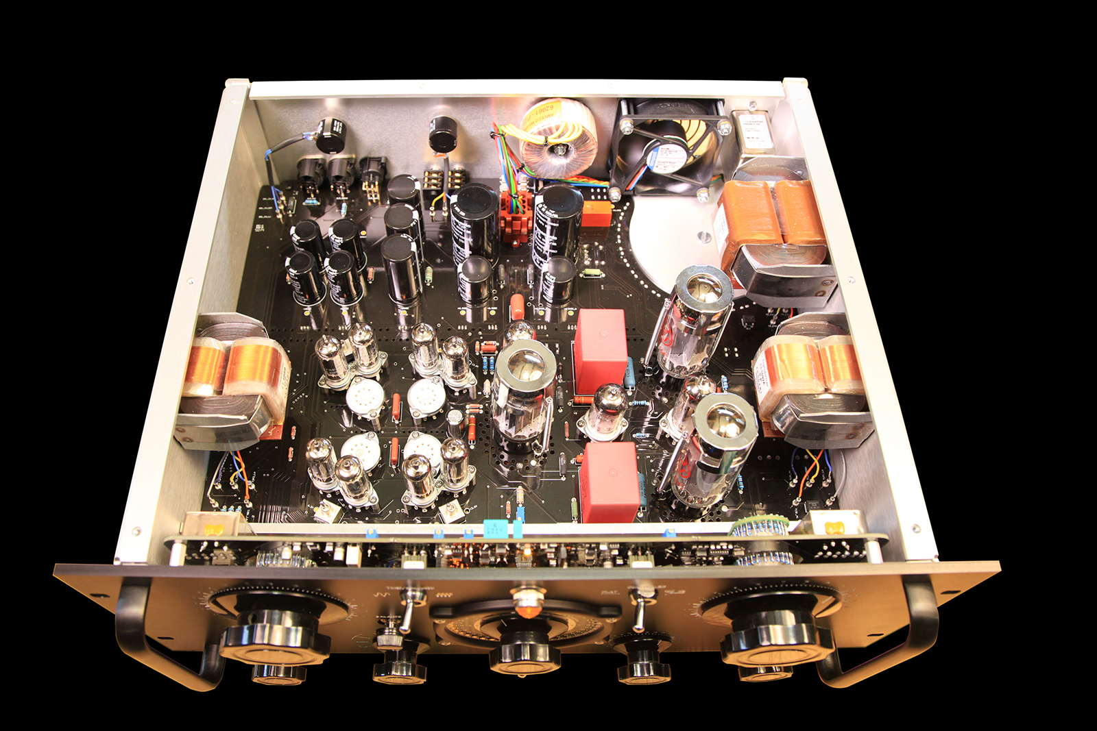
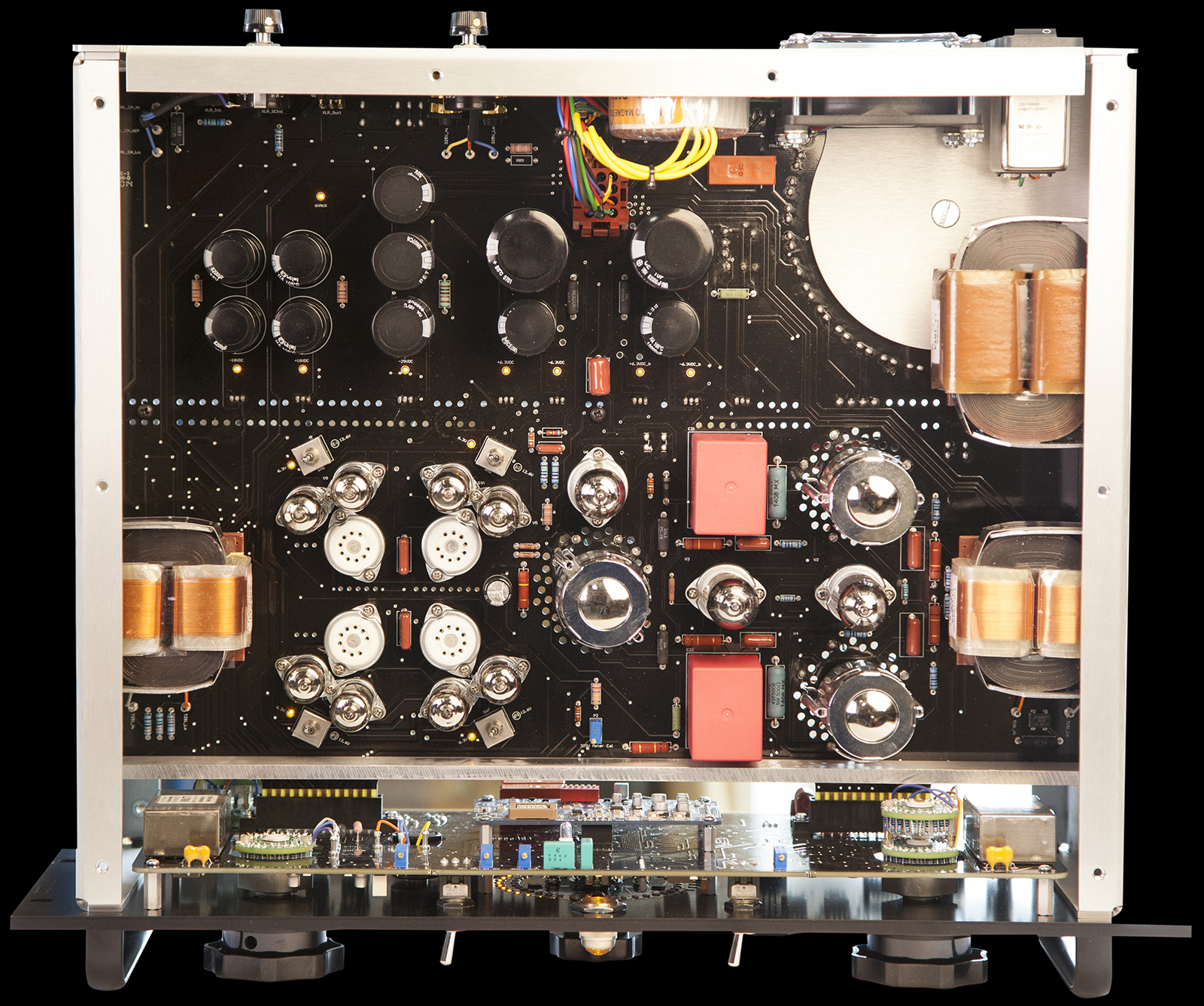
These photos are a little mediocre, but they’ll have to do for now. Hopefully they’ll do a decent job of conveying the build quality and attention to detail.
Click on each image to enlarge in a new window.
Front Panel

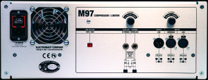
Rear Panel
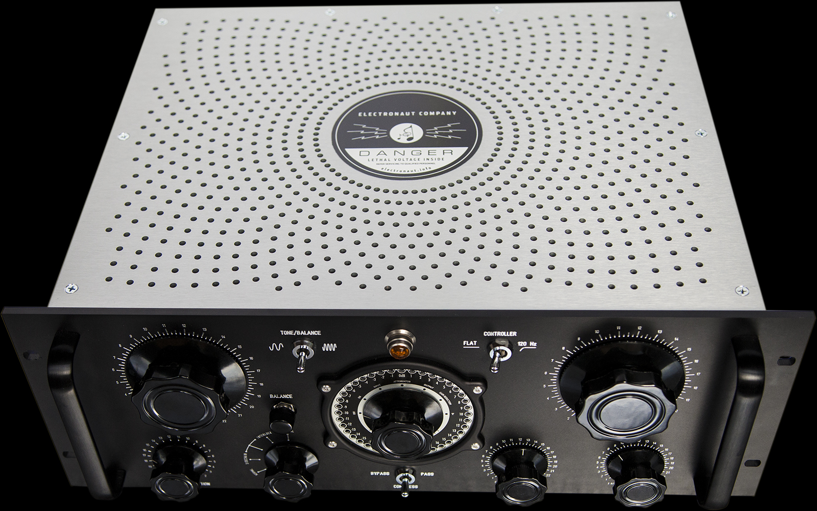
Top Cover

Top Cover, Naked
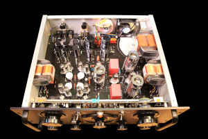
Internal Electrical Layout

-
List Price = $7,777 USD
Taking into account the sound and performance, wide array of features, improved usability, substantial build cost, and how the M97 stacks up to the other currently available vari-mu type compressors ranging from $8,000-$14,000 per channel, we think the M97’s price/performance ratio is excellent.
While we recognize that the price makes the M97 out of reach for many, we could not justify making the compromises that would have been necessary to reach a lower price point. The goal at the onset of this project was to try and raise the bar — to update what people expect from a vari-mu compressor. This is quite a different goal than introducing a mainstream product for the widest possible market, and accomplishing that goal required that quality and performance be prioritized over price.
Availability
Both the Mixing and Mastering version of the M97 Compressor/Limiter are available now with no difference in price.
Lead Time
Lead-times are quoted at the time of order, but are typically about 4-6 weeks from the receipt of payment.
Purchasing Details
A quote including an estimated ship date will be issued upon request. We prefer to receive payments via wire transfer or cashier’s check, but other payment arrangements may be made if requested prior to ordering.
Thank you!!
-
M97 USER’s MANUAL
The User’s Manual is available here.
FAQ
Will there be a stereo M97?
The single channel M97 has 14 tubes, 7 transformers, and weighs 33 lbs (15 kgs) — a lot, even for a 14″ deep 4U enclosure! A stereo unit would require 8 more tubes and two more transformers. We’re not going to say never, but it’s definitely not in the cards right now!
All the knobs are stepped switches except the Attack and Release controls, which are continuously-variable potentiometers. Can you make a mastering version with stepped Attack and Release controls?
YES. The Mastering version is now available! The only difference is that the Attack and Release controls are stepped switches instead of continuously variable pots, offering 12 independently controllable time constants.